
LED Work Light Heat Dissipation: Why Thermal Design Affects Lifespan
An LED work light does not usually die because its chips burn out. It dies because nobody managed the heat those chips generate, and the first casualty is almost never the thing the box advertises. Every watt pushed through an LED becomes light plus heat, and in a sealed, vibration-hardened housing packed against a machine’s hydraulic lines and sun-baked steel, that heat has nowhere obvious to go. Understanding led work light heat dissipation is the difference between a buyer who reads a “50,000 hour” label as a promise and one who reads it as a conditional statement that the thermal design either honours or breaks. For procurement managers and fleet spec writers assessing high-wattage work lights, thermal engineering is where the real longevity conversation happens — before the lumens, before the price, before the certificate on the wall.
Key Takeaways
- Heat, not the LED chip itself, is the limiting factor in work-light life: junction temperature drives lumen depreciation, colour shift and, most of all, driver-electronics failure.
- A die-cast aluminium housing with integral heat-sink fins is a thermal component, not just a rugged shell — its mass and fin geometry set how much heat it can dump at a given ambient.
- 에이 “maintains output at 85 °C ambient” rating is a much stronger claim than a bare junction-temperature limit, because it accounts for the whole heat path from chip to surrounding air.
- The driver is a second, faster failure clock than the LEDs; electrolytic capacitors age roughly in line with how hot they run, so thermal layout around the driver decides much of real service life.
- Field reality edits the lab number: dust blanketing the heatsink, an enclosed mount and low airflow all raise operating temperature, which is why thermal testing and seal design belong in the same specification.
Why Heat Is the Real Limiting Factor in an LED Work Light
The semiconductor business has a well-worn rule: reliability is a temperature problem. In an LED fixture, electrical input converts partly to light and substantially to heat at the chip’s junction. That junction temperature governs three things a buyer cares about. It sets how quickly the LED loses output over thousands of hours — lumen depreciation accelerates as junction temperature climbs, so two identical chips run at different temperatures will not dim at the same rate. It drives colour shift, the slow drift of the beam’s hue that matters more in tuned applications than in a warehouse flood, but still signals thermal stress. And it throttles instantaneous output, because a hot LED produces fewer lumens per watt than a cool one, which is exactly why a well-heat-sunk lamp can hold its rated output where a cheap one quietly fades as it warms up through a shift.
None of this is exotic. The engineering question a buyer should put to a supplier is not “what is the chip rating” but “what temperature does the chip actually run at inside this housing, in this ambient, on this machine.” That single reframe moves the conversation from marketing numbers to physical design, and it is the backbone of how we think about validating longevity claims in our companion piece on LED work light lifespan and long-life claims.
How the Housing Moves Heat: Die-Cast Aluminium and Fin Geometry
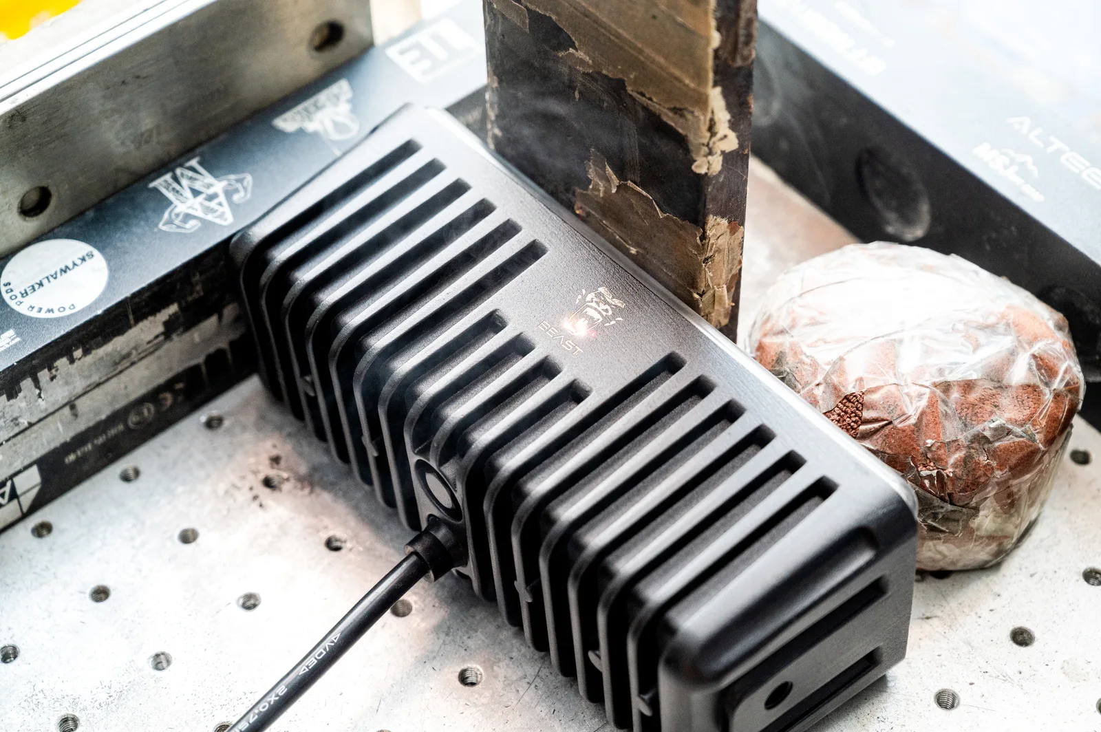
In a ruggedised work light there is no fan, and there is no separate heatsink bolted on as an afterthought. The housing is the heatsink. That is why the material and the casting matter so much: a die-cast aluminium housing carries the LED board’s heat into its own mass and throws it to the surrounding air through its surface area. Aluminium’s thermal conductivity, the thickness of the walls around the LED pad, and the internal and external fin geometry together set a thermal resistance — the number of degrees the junction will run above ambient for every watt dissipated. Undersize that path and every downstream reliability number in the datasheet becomes optimistic.
Two design consequences follow. First, mass is not waste: the “heavy for its size” work light is often the well-engineered one, because thermal capacity and surface area buy headroom exactly when a machine is working in still air on a hot day. Second, the interface between the LED board and the housing is a real thermal joint that has to be made with proper interface material and clamping pressure, not air gaps; a brilliant fin design is undone by a poor contact surface at the chip. XRLL builds its work-light housings as die-cast aluminium with integral heat-sink fins specifically so the mechanical enclosure and the thermal path are one part, sharing the same quality gate on the line.
What “Maintains Output at 85°C Ambient” Actually Proves
Spec sheets quote temperature in at least two different places, and buyers should know which one they are reading. A maximum junction temperature — often 105 or 125 °C for a chip — tells you the semiconductor’s own ceiling, not the fixture’s behaviour. A far more useful and harder claim is an ambient rating: what surrounding temperature the finished lamp can sit in and still hold its rated output without thermal derating. When a work light is specified to maintain output at 85 °C ambient, it is making a whole-system promise — chip, board, interface, housing, fins and driver all included — that the entire heat path still clears the generated heat even when the air around the lamp is genuinely hot. That matters on construction and mining equipment, where a lamp mounted near an exhaust, a hydraulic circuit or sun-loaded steel can see local air temperatures no office ceiling ever reaches.
The honest reading is comparative: an ambient rating gives you a number you can reason about against your own machine, whereas a junction ceiling is mostly a component datasheet fact the supplier could quote whether or not their housing earns it. Ask any supplier which they publish, and treat a bare junction limit presented as a durability claim as a question, not an answer.
The Driver Is a Second, Faster Thermal Clock
The LED chip is often the most thermally tolerant part in the fixture. The driver — the electronics that convert the machine’s 9-36 V input into regulated current for the LEDs — is usually the first thing to die, and heat is why. Switch-mode drivers rely on electrolytic capacitors whose life shrinks dramatically with every 10 °C rise in their operating temperature; the same thermal abuse that only slightly speeds LED depreciation can halve capacitor life several times over. A driver cooked against a hot housing fails long before the chips reach their rated hours, which is why the widely quoted “50,000+ hour” figure is properly read as a joint LED-and-driver rating achieved only when the whole assembly is kept inside its thermal design point.
Good thermal design gives the driver its own path to the housing, places heat-generating components on thermally conductive pads, and selects capacitor temperature ratings that match where they actually sit — not the coolest bench, but the worst corner of the assembly at the worst ambient. Component quality upstream matters too: standard chips from the OSRAM and Cree tiers behave predictably thermally, whereas unbin substituted chips vary in forward voltage and heat output in ways that quietly overload a driver designed for a spec the parts do not meet.
How Dust and Mounting Edit the Thermal Budget in the Field
A heatsink only works if it can trade heat with air, and the field does two things to that exchange. It blankets the fins. On mining and construction equipment, abrasive dust cakes onto the housing and into the fin channels, adding an insulating layer and blocking airflow — a phenomenon our mining and quarry durability guide covers from the ingress side; thermally, a dust-blanketed lamp simply runs hotter, which accelerates depreciation and driver ageing at once. Sealing design and thermal design are therefore partners, not rivals: an IP68 fixture that keeps dust off its external fins preserves the heat path that a “dust protected” fixture slowly loses.
Mounting position edits the budget too. Bolting a lamp to a warm surface, enclosing it behind a guard or in a recess, or clustering several on one bracket all reduce the effective ambient and airflow the design assumed. This is why a competent supplier states a maximum ambient and a mounting orientation, and why a fleet that re-homes lamps into tighter spaces should expect a different thermal reality than the test bench measured.
How a Real Manufacturer Tests the Thermal Design
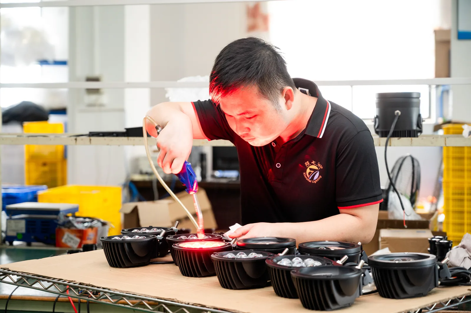
Thermal claims are only as good as the production tests behind them, and a heavy-duty lighting factory treats them as standing line checks rather than a one-time certificate. The relevant tests are high-low temperature aging, where finished units run through hot and cold cycles to flush out weak interfaces and under-rated components; constant temperature-and-humidity stress, which combines heat with moisture to test sealing and corrosion at the same time; and light-output verification at temperature, so the “maintains output” claim is measured, not asserted. XRLL’s nine-stage QC flow builds these in as routine steps — high-low temperature aging sits alongside chip incoming inspection, IP68 sealing, vibration and shock, and a pre-shipment final check — which is the architecture that produces per-lot evidence instead of a launch-year report that no sample from your order was ever held to.

Thermal-Design Elements and the Right Question for Each
| Thermal Element | What It Protects | Question to Ask the Supplier |
|---|---|---|
| Die-cast aluminium housing | Sets the primary heat path and thermal mass from chip to air | Is the housing sized as a heatsink, and what maximum ambient does it hold rated output at? |
| External / internal fins | Surface area available to shed heat in still air | How is fin geometry validated, and how does dust blanketing change it? |
| LED-to-housing interface | The contact resistance between board and heatsink | What interface material and clamping method is used, and how is it QC’d? |
| Driver layout and capacitor rating | The fastest-failing, most heat-sensitive components | What temperature-rated capacitors are used, and are they thermally isolated? |
| Sealing (IP68) | Keeps insulating dust and moisture off the heat path | Does the seal protect the fins and interface, not just the optics? |
| Production thermal testing | Proves the design holds lot after lot | Is high-low temperature aging a standing line check or a one-off type test? |
The Buyer’s Thermal-Design Checklist
- Ask for an ambient rating (e.g. maintains output at 85 °C), not only a maximum junction temperature.
- Confirm the housing is a designed heatsink: die-cast aluminium, fin geometry, and adequate thermal mass for still-air duty.
- Require the LED-to-housing interface method and its QC, because a good fin design is undone by a poor contact surface.
- Probe driver capacitor temperature ratings and layout — this is what most often decides real service life.
- Verify chip provenance (오스람 / Cree tiers with verified bin codes); mismatched bins overload the thermal design quietly.
- Check that sealing protects the external heat path, since dust blanketing the fins raises the whole fixture’s operating temperature.
- Insist that high-low temperature aging is a standing production check you can get per-lot evidence for, not a launch certificate.
Get the thermal spec behind the lifespan number
Send your mounting position, ambient conditions and drive cycle. XRLL engineers document the housing, driver and production thermal testing behind each work-light recommendation, with OEM configuration options, and reply within 24 시간.
Frequently Asked Questions
Why does heat reduce an LED work light’s lifespan?
Because LED output and electronics reliability both fall as temperature rises. Higher junction temperature speeds lumen depreciation and colour shift in the chips, and it dramatically shortens the life of the driver’s electrolytic capacitors — often the first part to fail. Managing heat keeps the whole assembly inside the conditions under which its rated lifespan is actually achievable, which is why thermal design, not the chip alone, sets real service life.
What makes die-cast aluminium a good heatsink for work lights?
Aluminium conducts heat well and can be die-cast into a single housing that is both the rugged mechanical shell and the thermal path. Its mass absorbs heat and its moulded fins add surface area to shed it to the air, with no fan required. That is why a heavier die-cast housing is usually a better-engineered one thermally — it gives the driver and chips headroom on a hot, still-air machine rather than only on a bench.
What does “maintains output at 85°C ambient” mean for buyers?
It is a whole-system rating: at 85 °C surrounding air the finished lamp still delivers its rated output without thermal derating, accounting for the chip, board, interface, housing and driver together. That is far more useful than a bare maximum junction temperature, because it lets you reason about your own machine’s real operating heat — near exhausts, hydraulics or sun-loaded steel — instead of a component datasheet limit.
Does dust really affect how hot a work light runs?
예, significantly. A layer of dust on the fins acts as insulation and blocks airflow, so the heat the design assumed would leave the housing stays in it, raising junction and driver temperature and accelerating both lumen loss and capacitor ageing. This is why sealing and thermal design belong in the same conversation: an IP68 fixture that keeps abrasive dust off its external fins keeps the heat path working over years of service.
How can I tell if a supplier actually tests thermal design?
Ask what runs on the production line, not just which certificates exist. A manufacturer that treats high-low temperature aging, constant temperature-and-humidity stress and light-output verification at temperature as standing per-lot checks can show evidence for your specific order. A supplier whose thermal proof is a one-time type-test from the launch year cannot, and that distinction predicts real-world reliability better than any marketing lifespan number.


